TASKLED - Smart LED drivers
|
|
home > products (hallsw)
NOTE: Updated to use bi-directional Hall Sensor 2 June 2012
Hallsw Power Switch:
Refer to the following picture:
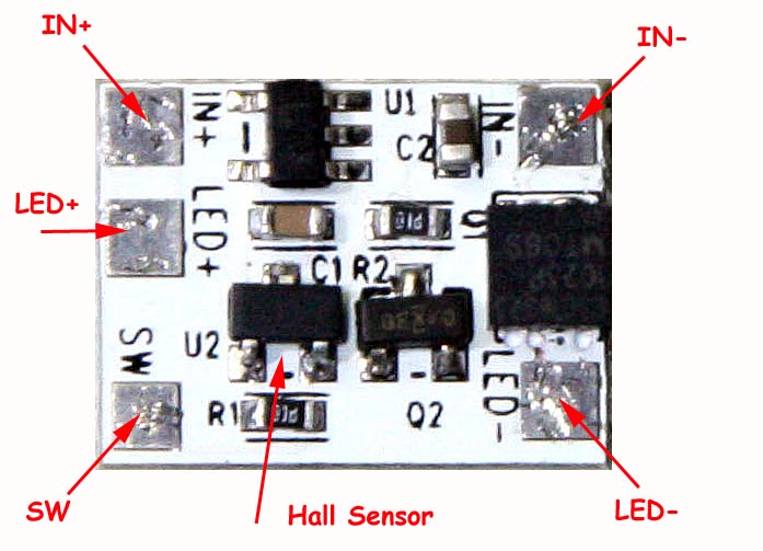
The bottom of the Hallsw board has no components and would typically mount using the supplied double sided adhesive thermal pad material to a heatsink (body of the light). HALLSW shipped on/after 2 June 2012 have a bidirectional Hall Sensor (like the HALLTG board) so either N or S will activate the sensor. Prior to 2 June 2012, the Hall Sensor (U2) can be activated by the N side of a magnet from above or the S side of a magnet from below the PCB.
The power FET (Q1) has vias under the FET to the bottom side of the PCB to provide a thermal path in high current applications. The on resistance of the FET is very low (typically less than 6 milliohms) and even at 10A total dissipation would only be (10 x 10 x 0.006) = 0.6W, which can easily be handled by a modest heatsink or attachment to the body of the light.
The supplied thermal pad material is nominally 0.25mm thick, white in colour and will conform to the heatsink and PCB surfaces to provide an excellent thermal path. Please ensure the heatsink and bottom of the HALLSW are cleaned of any grease or contaminants that would prevent the adhesive from properly bonding. Pressure should also be applied to help set the adhesive, refer to the datasheet for more information.
The thermal pad material (Li98 100 0.25mm) specifications can be found in the datasheet a copy of which is available here. The Li98 material provides a good compromise between the cost of the material and its thermal performance. The material is white in colour and has a protective cover on both sides that must be removed to expose the adhesive. Note, it is recommended to remove the Red protective material first and fix the pad to the heatsink or the HALLSW prior to removing the white protective material. The adhesive is an acrylic base and takes up to 24 hours for fully cure/set. After a few thermal cycles and 24 - 48 hours the bond will become stronger and the thermal conductivity will improve.
Connecting the Hallsw to a LED or bulb (direct driven):
The following shows how the Hallsw board is connected to a simple load like a direct driven LED.
Connecting the Hallsw to a LED driver:
The following shows how the Hallsw board is connected to an active load such as a LED driver.
Connecting the Hallsw to a TaskLED flex driver:
The following shows how the Hallsw board is connected to a simple load like a direct driven LED. In this case the Hallsw SW output signal and the FET output is not used.
SWA is also called SW+ on the d2flex driver.
SWB is also called SW- on the d2flex driver and SWG on older versions of the maxflex driver.
Note it is very important to wire the IN- of the Hallsw board to the SWB/SW-/SWG connection point on the flex drivers. This is to provide a 'quiet' ground connection for the Hallsw board.
Connecting the Hallsw to a inductive load such as a HID driver:
When an inductive load needs to be switch, the an external diode is require to protect the FET from inductive spikes. Inductive loads such as a relay, a HID driver, solenoid etc require the addition of the diode as shown below. Any small signal silicon diode can be used, e.g. 1N4148.
Here is a Youtube video showing the Hallsw board in action. NOTE, HALLSW shipped on/after 2 June 2012 have a bidirectional Hall Sensor and will activate with either the N or S of the magnet (same as the HALLTG board):
home | products | technical | order products | contact
©2026 TaskLED. All Rights Reserved.