TASKLED - Smart LED drivers
|
|
home > products (piezotg)
Piezotg Power Toggle Switch:
Refer to the following picture:
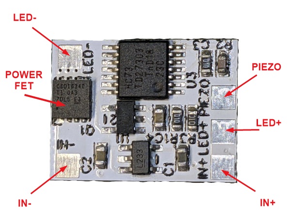
The bottom of the Piezotg board has no components and would typically mount using the supplied double sided adhesive thermal pad material to a heatsink (body of the light). The Piezo switch can be wired several inches from the Piezotg board.
Note that the Piezotg board is a toggle action switch. When power is first applied the Piezotg board will power up with the FET turned off, this is guaranteed by design. Pressing the Piezo switch will toggle the FET to the on state. To turn the Piezotg board back off, press the Piezo switch again. This action can be repeated as needed, hence the Toggle action.
Note that since the Piezotg board is a toggle action switch, care must be taken to not accidentally turn on the board with an accidental press of the Piezo switch when the light is being stored.
The power FET (Q1) has vias under the FET to the bottom side of the PCB to provide a thermal path in high current applications. The on resistance of the FET is very low (typically less than 6 milliohms) and even at 10A total dissipation would only be (10 x 10 x 0.006) = 0.6W, which can easily be handled by a modest heatsink or attachment to the body of the light.
The supplied thermal pad material is nominally 0.25mm thick, white in colour and will conform to the heatsink and PCB surfaces to provide an excellent thermal path. Please ensure the heatsink and bottom of the Piezotg are cleaned of any grease or contaminants that would prevent the adhesive from properly bonding. Pressure should also be applied to help set the adhesive, refer to the datasheet for more information.
The thermal pad material (Li98 100 0.25mm) specifications can be found in the datasheet a copy of which is available here. The Li98 material provides a good compromise between the cost of the material and its thermal performance. The material is white in colour and has a protective cover on both sides that must be removed to expose the adhesive. Note, it is recommended to remove the Red protective material first and fix the pad to the heatsink or the Piezotg prior to removing the white protective material. The adhesive is an acrylic base and takes up to 24 hours for fully cure/set. After a few thermal cycles and 24 - 48 hours the bond will become stronger and the thermal conductivity will improve.
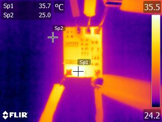
The following thermal picture shows the piezotg board running in air and 4A. Sp1 is indicating the FET temperature (35.7C), Sp2 is essentially ambient temperature (25C). This is after 10 minutes and the board has reached steady state.
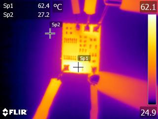
The following thermal picture shows the piezotg board running in air and 7A. Sp1 is indicating the FET temperature (62.4C), Sp2 is essentially ambient temperature (27.2C). This is after 10 minutes and the board has reached steady state.
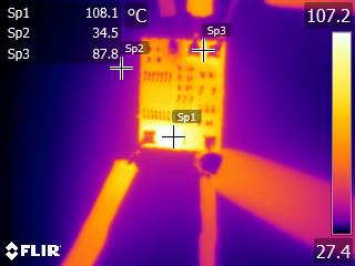
The following thermal picture shows the piezotg board running in air and 10A. Sp1 is indicating the FET temperature (108.1C), Sp2 is essentially ambient temperature (34.5C). Sp3 is the copper trace running between IN+ and LED+. This is after 10 minutes and the board has reached steady state.
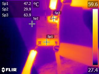
The following thermal picture shows the piezotg board still running at 10A but after a further 10 minutes. The board is mounted via a thermal pad to an aluminium heatsink. Sp1 is indicating the FET temperature (47.2C), Sp2 is essentially the heatsink temperature (29.9C). Sp3 is the copper trace running between IN+ and LED+.
Connecting the Piezotg to a LED or bulb (direct driven):
The following shows how the Piezotg board is connected to a simple load like a direct driven LED.
Connecting the Piezotg to a LED driver:
The following shows how the Piezotg board is connected to an active load such as a LED driver.
Connecting the Piezotg to a inductive load such as a HID driver:
When an inductive load needs to be switch, the an external diode is require to protect the FET from inductive spikes. Inductive loads such as a relay, a HID driver, solenoid etc require the addition of the diode as shown below. Any small signal silicon diode can be used, e.g. 1N4148.
home | products | technical | order products | contact
©2026 TaskLED. All Rights Reserved.