TASKLED - Smart LED drivers
|
|
b3Flex:
Drivers shipped after Jan 20, 2014:
Drivers shipped prior to Jan 20, 2014:
B3Flex 3D Step file: Click -> B3Flex.step to download.
Efficiency Measurements:
As with any buck driver, efficiency is highest when input voltage is closer to output voltage and also with higher voltages. So, a 1 LED (3.3V Vf) system will be less efficient than say a 3 LED (10V Vf) system.
b3Flex requires the input voltage to be higher (headroom) than the total LED Vf to ensure it is in current regulation mode. At 3000mA, the b3Flex requires a minimum of 1.1V headroom to regulate, so for 2 LEDs with Vf of 3.3V at 3000mA, the minimum operating voltage would be (2 x 3.3V + 1.1V) = 7.7V. Below 7.7V the b3Flex would no longer be able to provide 3000mA to the LEDs and the output current would drop.
The guaranteed minimum operating input voltage for the b3Flex is 6V for 3A output to a single white LED.
Typical measured efficiency values are shown in the following graphs. Using typical XML Vf of 3.3V (1 LED), 6.6V (2 LED), 9.9V (3 LED) and 13.2V (4 LED) at 3A. The curves below are actual measured values using a precision electronic load and power supply both with 4 wire kelvin probes. Voltage settings for the tests were 6V, 9V, 12V, 15V and 20V (emulating discharged 2, 3, 4, and 5 series li-ion battery packs).
As can be seen from the table, in a 3 LED, 4 Li-Ion system, the b3Flex will be typically running around 94% efficient at 3A output.
So, assuming 3 LEDs with a total Vf of 10V (Cree XML) at 3000mA we can calculate driver power dissipation (loss) as:
10V x 3A x 0.06 = 1.8W
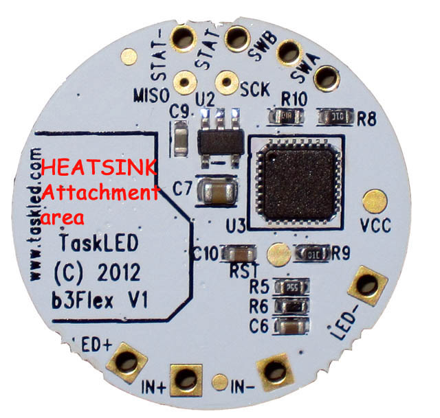
It is HIGHLY recommended that the b3Flex be attached to a heatsink/thermal path using the outlined polygon area in the following picture.
Magnetic Field Warning:
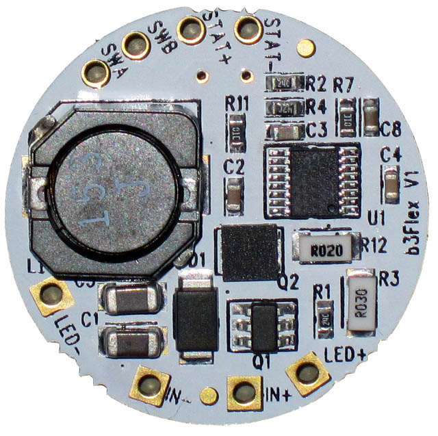
The b3Flex is a switching regulator based driver and contains a shielded Inductor (L1 in the picture above). Strong external magnetic fields such as from a magnet used to operate a Hall sensor or Reed switch can interfere with the Inductor's operation. It is recommended to maintain a minimum of 1" from the Inductor and any external magnet. If the magnet is very powerful, then the distance needs to be increased (more than 1") as needed to minimise interference to the Inductor.
Potting Warning:
Areas of the circuitry on b3Flex utilise high impedance paths and if potting (not required) is to be utilised, the user must ensure than the compound is non-conductive and non-capacitive otherwise correct operation may be compromised. A product like Artic Alumina epoxy will work well.
The following picture shows the top of b3Flex.
The X/Y position of the various solder pads/connection points is in the table below. X/Y position 0,0 is the center of the board. X/Y positions are in mils (0.001", so -75 means -0.075")
PAD |
X |
Y |
| STAT- | -75 | 440 |
| STAT+ | 60 | 440 |
| SWB | 190 | 405 |
| SWA | 285 | 340 |
| LED+ | -210 | -380 |
| IN+ | -60 | -425 |
| IN- | 165 | -405 |
| LED- | 395 | -185 |
Input voltage connects to IN+ and IN-.
The LED(s) connect to LED+ and LED- (NOTE: LED- is NOT electrically the same as IN-).
The control switch connects to SWA and SWB (SWB is electrically the same as IN-). The switch only switches a control signal and carries at most 350microamps.
The status LED (optional) connects to STAT and STAT- (STAT- is electrically the same as IN-). The b3Flex provides 3V via a 100 ohm resistor to the status LED, so it can drive a Red/Green or Amber 3mm/5mm LED.
The following picture shows the bottom of b3Flex.
Current Regulation:
The b3flex is a DC:DC converter that uses constant current regulation hardware.
With V1.4 of the firmware, a change was made to improve current regulation accuracy for low current levels below 500mA. The firmware switches to a mix of constant current regulation (500mA constant current) and PWM running at 400Hz. The PWM duty cycle will be varied as needed to reduce the average LED current.
Additionally the optional configurable low current L1 now uses 400Hz PWM with 200mA current pulses to provide a choice of 50mA (500mA 10% duty cycle) and 40,30,20 and 10mA (200mA at 20%,15%,10% and 5% duty cycle, respectively).
Thermal Considerations:
The b3flex is a very efficient constant current buck driver, but when run with multiple LEDs at high current, losses (heat) will require the driver to be attached to a heatsink to provide a mechanism to dissipate that excess heat.
The recommended material to attached the driver to a heatsink is a 2 part thermal epoxy such as Arctic Alumina (the epoxy, NOT the paste).
The picture to the left shows the area of the b3flex that requires attachment to a heatsink.
The entire area bounded by the polygon should be thermally bonded to a heatsink using either non-conductive thermal epoxy (such as Arctic Alumina 2 part epoxy) .
The main heat losses occur from components that are on the other side of the PCB within the polygon area. The PCB has multiple drilled/plated holes that provide a thermal path from the other side of the board to this side. Please NOTE, the entire polygon area is NOT at the same potential, so the soldermask is providing electrical isolation to the heatsink. Do NOT scratch the soldermask to expose the underlying copper or a short through to the heatsink is possible.
![]()
The heatsink path can be a machined pedestal in the body of the light to provide a place to attach the b3flex or alternatively an aluminium shim can be purchased along with the b3flex that would allow easy attachment to a flat heatsink surface.
home | products | technical | order products | contact
©2026 TaskLED. All Rights Reserved.